
DIY Photo Frame Using a Raspberry Pi
Recently, I decided to do something with the large collection of photos and videos I had taken at weddings, on trips, and while travelling. These days, it is far too easy to take hundreds of photos because memory is cheap and most of us carry a pocket camera in our phones. Printing out photos is one option, but it feels too static to me. As a web developer, I like things to be dynamic and interactive.
Looking around, I found a Raspberry Pi that I had bought for another project, which I had started but did not have the budget or time to finish. Looking at it, I realised it had a display connector. So I started searching for Raspberry Pi-specific screens. After a bit of searching, I found that they existed but were not cheap. The main issue was that they were generally quite small, usually 7 inches or under, whereas I wanted at least 10 inches. While I was debating whether to spend the money, I came across an old laptop with a screen about the size I wanted. I started researching whether it was possible to connect the Raspberry Pi and the screen together, perhaps by finding a wiring diagram and soldering an adapter. After a bit of research, I came across a website (sorry I do not remember the URI) that showed a "laptop screen video driver board". As it turns out, you can buy a programmable board that turns a laptop screen into a normal monitor. Genius!
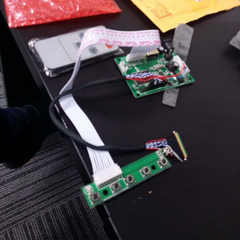
The laptop screen driver boards were relatively inexpensive as well, at least for some models. So I pulled apart the laptop and found the exact screen model number was "LP156WH2". This is a great board because there is no additional backlight power cable (it's all part of the same wiring loom as the signal data), some LCDs require a separate power wire and circuit board for the lighting. I suspect this one is LED backlit, whereas the ones with separate power wires use a more traditional backlight. There turned out to be a few different boards available for my LCD screen model: some cheaper ones with just VGA, some with VGA, DVI, and HDMI, some with a remote, and some even with TV tuners (many ideas filled my mind for future projects as there is so much potential). I settled on a unit with a remote, a single HDMI, and a Realtek chip.
My reasoning for picking this board was:
- The main chip is a Realtek, a known brand that might last longer.
- The circuit board was quite small.
- The eBay auction said it would work on 5 volts, the same voltage as the Raspberry Pi.
- The remote would be handy if I wanted to enclose it in a frame. More on this later.
- It had HDMI for the Raspberry Pi, so no bulky VGA-to-HDMI adapter would be required.
- It was only about $30-$35 NZD with shipping. Most of the dedicated Raspberry Pi screens were about $150-$200 NZD from memory, and only 7 inches.
The wait was on for the unit to ship from Hong Kong. Once the unit arrived, I grabbed the Raspberry Pi, the laptop screen, and a POE splitter, then started a few experiments to see what it was capable of. See my cat feeder post for more details on POE. First test: 5 volts. I set the POE splitter to its 5 volt option and attached it directly to the driver board. Success: it worked! Next, I tested running both the Raspberry Pi and the screen from the same POE splitter. At this point, I was still concerned about whether this would work. For those less familiar with POE, my injector gear is not the newer generation; it uses the older IEEE 802.3af-2003 specification, which is limited to 15.4 watts. Newer gear can provide up to 25.5 watts. I did a lot of research into the power draw of the screen and the Raspberry Pi, but I did not manage to get exact numbers. My backup plan was to use two POE splitters, one for the Raspberry Pi and one for the screen, but that would also require two Ethernet cables. I did not like that idea, but as a last resort it would still be better than plugging it into the wall. Wall outlets are rarely in the right place, and 12V or 5V wall wart cables can lose voltage quickly over longer distances, making the voltage unusable.
I grabbed a terminal strip, a few wired connectors I had made, and a Y power distribution cable to send power from the POE splitter to both the screen and the Raspberry Pi. It had a male DC jack for the tail into the POE power splitter, another DC jack for the screen driver board, and a micro USB cable for the Raspberry Pi. Then I plugged it into the POE splitter, but the screen only flashed and did not display anything. At this point, I thought there were two possible causes. One was that there was not enough power from POE to power both devices. The other was that the Raspberry Pi's power draw dropped the 5V supply too low for the screen and display driver to operate. One of the great things about POE is that you can see the power draw for each port. Sadly, the POE injector I have only has a serial input, and my USB serial adapter does not work with it. I do have a smaller POE injector with Ethernet that I could have used to check the draw, but I suspected the combined load was causing the 5 volt setting to fail. I decided to investigate that path first. I suspected this was the case because the website for the display driver, translated from Mandarin, mentioned only 12V as the operating voltage, which differed from the eBay auction.
Since my hunch was that the screen was not working on 5 volts, I tried running the injector output at 12 volts and using a DC-DC converter to drop the voltage to 5 volts for the Raspberry Pi. The next challenge was finding something to drop the voltage. It did not take long to realise that an automotive phone charger was a good candidate. Cars run on 12V, and many car phone chargers accept a wide range of voltages because trucks sometimes run on 24V. I grabbed a spare one from a drawer and found an old cigarette lighter extension cord where I had already cut the male end off for this type of testing. I connected this to the terminal strip Y connector I already had in place and plugged everything together. The moment of truth: would this be as tidy as I had pictured, with only a single Ethernet cable attached? I switched the POE splitter up to 12 volts and plugged it in. Success! Both devices worked perfectly.
The next weekend, I did some research and found relatively cheap, very small, prebuilt 12V-to-micro-USB units. Once again, they were intended for cars, and the local Jaycar had them in stock. This meant I would not need a bulky cigarette lighter socket and automotive phone charger inside the enclosure. Since this project was going on the wall, I wanted it to be as clean and minimal as possible. I went to our local Jaycar Electronics store and grabbed a Y DC-DC power cable, a female DC power jack, and one of the 12V-to-micro-USB units.
Ready for the final circuit test, I put everything together, and it worked. The next step was the frame. As you might have guessed, I decided to mount it in a photo frame intended for printed photos. I liked this idea as I had seen an episode of the show Hak5 where they had computers on the wall inside photo frames (so you could see the computers working inside on the wall through the glass). I also liked combining the old with the new. There is something elegant about a photo frame, but I did not like its static nature. The next challenge was to find a photo frame that could fit the screen. One of the major issues was the dimensions and aspect ratio, as most laptop screens are much wider than printed photos. I looked around for quite a while, then took the screen measurements to The Warehouse to try to find a suitable frame. After looking through the photo frames for a while, I found one that looked like it would fit the screen almost exactly, within a few millimetres. It was the only one, so I decided to take a chance. Luckily, they were on special, and I think I got two for $15 NZD each. It is useful to have a backup when modifying things, especially when glass is involved.
Once I got home, I started the test fit. This was a very tight fit, as the screen ended up being a few millimetres bigger than the frame. After removing the metal tabs that held the printed photo in place, I managed to carefully wiggle the screen in. This was difficult because I did not want to shatter or crack the LCD panel under pressure. Thankfully, the photo frame was not especially rigid, and one of the wooden corners expanded a little to let the screen fit. It was not noticeable. Since it was such a good pressure fit, I did not need much else to hold the screen in place. I then trimmed the cardboard inner bezel to fit the new wider screen and started to place the other components. I found it worked well to attach the components to the frame with Velcro strips and hold the cables to the outside of the frame with pins. I mounted the control board for the LCD driver board in one of the corners because it has the IR receiver on it, which meant the remote should work through the glass. This did render the buttons unusable, but that was not a problem because I had the remote.
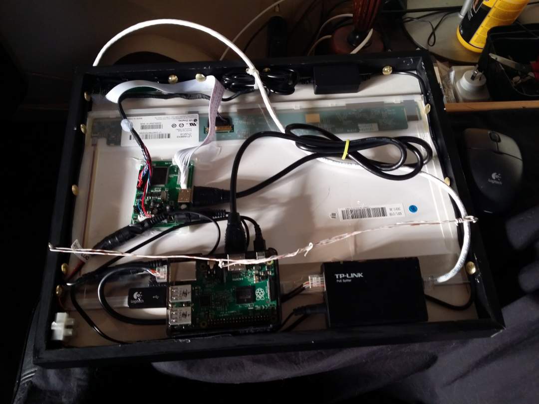
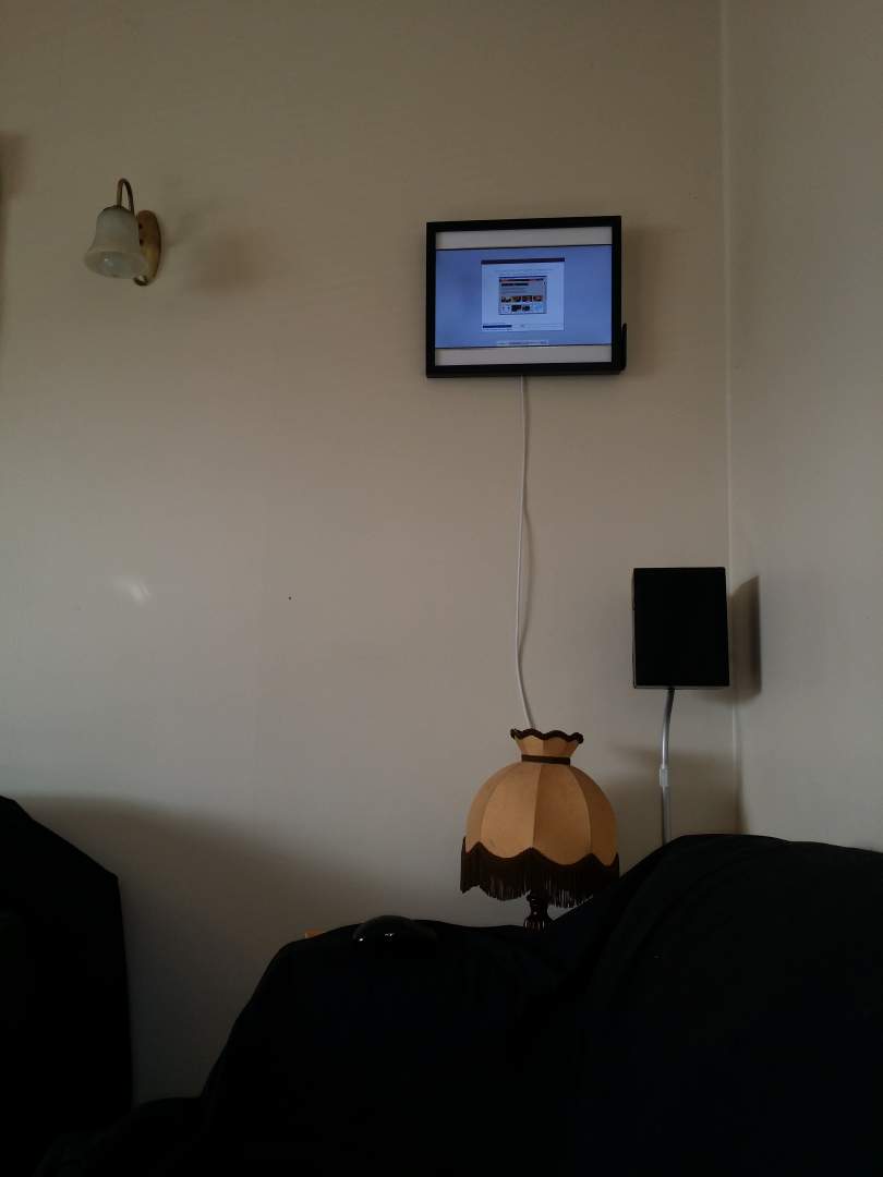
Next came the challenge of where to place it. After finding a good spot, I wired the Ethernet cable to it from the POE injector and started it up.
I intend to write a Python program to display photos from my NAS, which will be a good project for learning more Python.
I installed one of the standard Raspberry Pi operating systems with a GUI.
I decided to try an off-the-shelf solution for now, so I loaded the 8 GB microSD card with a few photos and went looking for a program.
After spending much longer than I expected, I finally managed to get something working.
I used a program called fbi (from memory, sudo apt-get install fbi), then added a script to launch it.
#!/bin/sh

sudo fbi -T 2 -noverbose --autozoom --random --blend 1 --timeout 6 /pictures/*
and added a simple start-up script /home/pi/.config/autostart/photos.desktop
[Desktop Entry]
Encoding=UTF-8
Type=Application
Name=FBI
Comment=
Exec=/photos.sh
StartupNotify=false
Terminal=false
Hidden=false
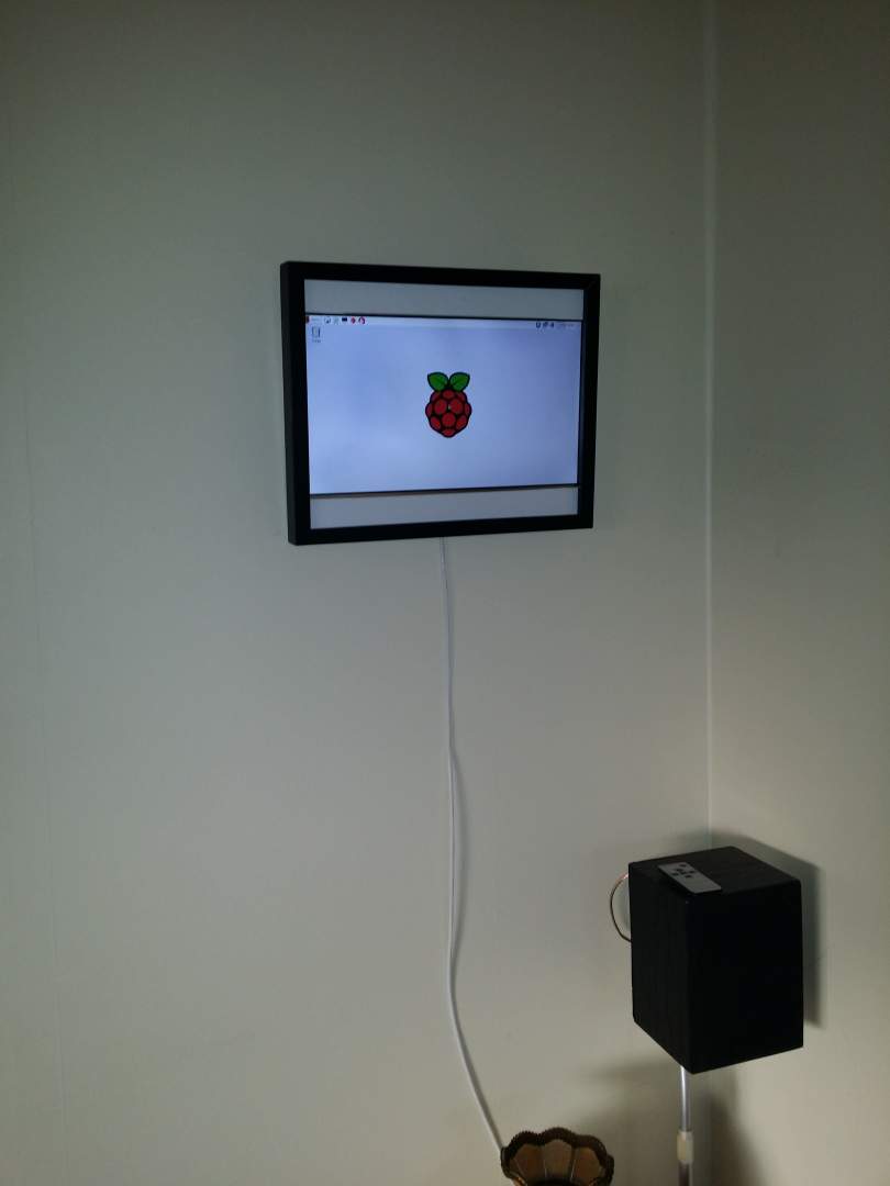
Photos look really nice on the screen.
It has excellent colour quality, and I am really happy with it.
Sadly, the viewing angle is awful, which is something I did not think about but is expected from a laptop screen. When looking up at it from an angle, the colours get inverted.
I am not sure this is correctable. I suspect there is some sort of polariser on the screen, or it may just be the design of the LCD itself.
The other issue is that fbi seems to lock up, freezing on a random photo after about three or four days, almost exactly the same amount of time after it was started.
All in all, it was a great project, and it is good to be able to reuse the screen instead of throwing it out.
Published: 28/08/2016 UTC
Updated: 18/06/2026 UTC
The opinions expressed on this website are my own and do not necessarily reflect the views of my employer. The posts on this website are provided "as is" with no warranties and confer no rights
Copyright © 2026 Jeremy Sells - See Site Terms/Disclaimer